When a modern dishwashing appliance fails to clean plates properly, runs endlessly, or aborts mid-cycle with a vague error code, homeowners often suspect a dead pump motor or a burned-out heating element. However, in contemporary US appliances engineered for strict federal energy and water efficiency, the true culprit is frequently a tiny optical component: the soil sensor module. Performing a dishwasher turbidity sensor replacement US style is one of the most cost-effective DIY home maintenance tasks you can undertake, often resolving stubborn wash issues without the expense of a professional service technician.
Modern dishwashers no longer rely solely on preset mechanical timers to wash dishes. To meet Energy Star guidelines and reduce overall gallon usage, major appliance manufacturers equip machines with optical soil-sensing technology. These turbidity sensors continuously analyze the clarity and temperature of recirculating water, signaling the electronic control module to extend, shorten, or repeat wash phases based on real-time contamination levels. When grease films, hard water mineral scale, or internal component short circuits blind this sensor, your appliance loses its ability to make intelligent cycle adjustments, leading to unsatisfactory performance and unexpected error halts.
Understanding the Role of the Optical Turbidity Sensor and Thermistor
A dishwasher turbidity sensor is an electro-optical monitoring device positioned directly within the appliance sump, situated in the main channel of recirculating wash water. In modern dishwashing machines sold across the United States, this component is rarely a standalone optical eye; instead, manufacturers combine two essential diagnostic tools into a single molded plastic housing projecting into the water chamber:
- Optical Phototransmitter and Phototransistor Receiver: An infrared light-emitting diode (LED) projects a focused light beam across a narrow water gap toward a photosensitive receiver. When clean water flows through the gap, nearly 100 percent of the light beam passes through unobstructed. As food particles, emulsified animal fats, sauce residue, and floating debris suspend in the wash water, the light beam scatters and dims. The sensor converts received light intensity into a proportional DC voltage signal sent straight to the main control board. High light transmission signals clear water, allowing the machine to advance to the final rinse phase. Low transmission signals cloudy water, instructing the machine to extend circulation, increase water temperature, or trigger an extra drain and refill cycle.
- Negative Temperature Coefficient (NTC) Thermistor: Built into the same housing next to the optical window, a solid-state thermistor acts as a temperature-dependent resistor. As wash water warms up, the thermistor’s internal resistance decreases in a precise, predictable curve. The main electronic control board continuously measures this electrical resistance to monitor incoming water temperatures, calculate thermal hold periods, and safely energize the internal heating element during wash and dry phases.
Because these dual diagnostic functions reside within a single sealed plastic housing, an electrical failure in either the optical light receiver or the temperature-sensing thermistor requires replacing the combined sensor unit. Understanding how these two circuits interact helps you diagnose wash anomalies accurately before spending money on unnecessary replacement parts.
Common Symptoms of a Faulty or Obscured Soil Sensor
Because the turbidity assembly directly influences both wash cycle timing and heating element activation, a degraded or obscured unit produces specific, recognizable operational symptoms. Recognizing these early signs saves hours of unnecessary troubleshooting elsewhere in the appliance.
1. The Dishwasher Runs Indefinitely or Fails to Advance
If your dishwasher gets stuck in a cycle and continues scrubbing for three to four hours past its normal expected runtime, the optical lens is likely coated in opaque grease or mineral scale. The central computer interprets the obscured optical path as dense, heavy food soil that refuses to wash away. Consequently, the machine locks itself into an infinite loop of heating, pumping, and circulating water, waiting indefinitely for water clarity to improve.
2. Aborted Wash Cycles and Cloudy Water Sensor Errors
When the main circuit board receives an out-of-range voltage signal from the phototransistor or thermistor—such as zero volts or an unstable, rapidly fluctuating signal—it triggers an automatic safety lock out to prevent dish damage or thermal runaways. Modern appliances notify the user by displaying visual fault codes on the front digital panel or blinking sequential LED patterns, commonly referenced in manual literature as a dishwasher cloudy water sensor error or soil sensor failure.
3. Poor Cleaning Performance on Standard Cycles
If an internal electrical failure causes the sensor output to remain fixed in a baseline “clear water” voltage state, the control board assumes wash water is crystal clear even when heavily polluted with oil, sauce, and solids. The machine prematurely terminates wash cycles, drains soiled water early, bypasses secondary rinse phases, and bakes floating food particles directly onto plates, cups, and silverware during the heated drying cycle.
4. Cold Wash Water and Wet Dishes at Cycle End
When the NTC thermistor section of the assembly experiences an internal open or short circuit, the main board cannot determine water temperature accurately. To prevent safety hazards like dry-firing the heating element without adequate water, the system logic disables the heater entirely. Wash cycles execute using cold tap water, leaving greasy films on dishware and failing to dry dishes at the conclusion of the program.

Diagnostic Codes Across Major US Appliance Brands
While the underlying optical and electrical physics remain identical across brands, individual manufacturers use distinct error codes to report turbidity and thermistor malfunctions. Understanding your brand’s specific diagnostic terminology streamlines the troubleshooting process.
| Appliance Brand | Primary Diagnostic Code | System Meaning | Recommended Action |
|---|---|---|---|
| Bosch / Thermador | E15 / E24 / E28 / Error 28 | AquaSensor light calibration out of bounds or turbidity limit exceeded | Clean optical prism face; inspect wiring harness; test thermistor resistance; replace sensor. |
| Whirlpool / KitchenAid / Maytag | F7-E1 / Code 7-1 | Turbidity sensor open circuit or baseline optical calibration failure | Inspect sump floor; check harness connections; measure pin resistance; clean or swap sensor. |
| GE / GE Profile / Cafe | FT / Error 16 / Code 16 | Fail Temperature or NTC thermistor signal communication dropout | Verify plug seating under sump bowl; check continuity; replace combination sensor module. |
| LG Electronics | nE / tE | Optical sensor signal abnormal or thermistor circuit reading out of logic limits | Clean lower sump housing; verify resistance across terminal pins using a multimeter. |
| Samsung | tE / tC / 6E | Temperature or soil sensor signal error detected by main PCB | Verify proper sensor seating in rubber sealing grommet; perform resistance bench test. |
Essential Safety Precautions and Diagnostic Tools
Working on major home appliances involves handling high-voltage electricity, sharp sheet metal, and pressurized water connections. Prioritizing safety and assembling the right diagnostic equipment before starting ensures a smooth repair experience.
Safety Guidelines
- Disconnect Electrical Power Completely: Always turn off the dedicated circuit breaker in your home’s main breaker panel or unplug the power cord directly from the wall outlet under the kitchen sink before removing access panels or touching electrical components. Never perform continuity or resistance testing on an energized circuit.
- Shut Off the Water Supply: Close the manual hot water shutoff valve located beneath the sink. This prevents accidental flooding if water lines are disturbed while maneuvering the dishwasher.
- Drain Residual Water from the Sump: Remove standing water in the filter basin using a sponge, turkey baster, or wet-dry vacuum. This keeps work areas dry and prevents water from dripping onto lower electronic modules when removing the sensor.
- Wear Cut-Resistant Gloves: Lower cabinet spaces contain exposed sheet metal edges, mounting brackets, and frame components with sharp burrs that can easily cause deep cuts.
Recommended Tools and Replacement Materials
- Digital multimeter equipped with fine needle probes for testing micro-terminal pins
- 1/4-inch nut driver or magnetic bit holder
- Torx drivers (specifically T15 and T20 sizes common on Bosch, Whirlpool, and Frigidaire units)
- Flathead and Phillips screwdrivers
- Needle-nose pliers
- Food-grade silicone lubricant (O-ring safe)
- White distilled vinegar or specialized liquid descaling agent
- Soft microfiber cloth and a soft nylon detail brush
- OEM replacement turbidity sensor assembly matched precisely to your model number
Locating the Turbidity Sensor in Popular Dishwasher Models
The exact physical location of the turbidity sensor varies depending on the manufacturer’s mechanical engineering choices and chassis design.
1. Access from Inside the Tub (Sump Filter Basin)
In many recent dishwashers, the optical sensor tip is visible directly inside the bottom filter housing. By lifting out the coarse filter mesh cylinder, fine micro-filter screen, and lower spray arm assembly, you can observe a small clear or dark plastic nub protruding horizontally or vertically into the sump cavity. On select models, this sensor module can be released and replaced directly from inside the tub by unfastening top retaining screws or releasing plastic locking tabs.
2. Access from Beneath the Machine (Under-Sump Exterior)
In most mid-range and high-end models (including predominant Whirlpool, KitchenAid, GE, and Bosch platforms), the sensor mounts horizontally through the side wall of the lower plastic sump body beneath the tub frame. Reaching this area requires removing the toe kick plate and sound insulation at the bottom front of the appliance. On compact or fully enclosed units, you may need to disconnect the mounting screws securing the dishwasher to the countertop, slide the appliance forward 10 to 12 inches, and tilt it onto its back or side to access the lower sump harness easily.
Method 1: In-Place Cleaning and Scale Removal
Before purchasing a replacement part, always check if the existing sensor is simply blinded by organic fat film, detergent scum, or hard water mineral deposits. An optically obscured sensor produces the same error codes and behavior as a dead electrical component.
- Expose the Optical Chamber: Remove the lower dish rack. Rotate the central mesh filter assembly counterclockwise and lift it straight out of the sump recess. Drain any remaining stagnant water using a sponge.
- Inspect the Lenses: Direct a bright flashlight into the lowest chamber of the plastic sump. Locate the twin plastic prongs or optical window of the turbidity sensor. Check for cloudy white calcium build-up, greasy film, or trapped food particles between the lenses.
- Apply Descaling Solution: Soak a soft microfiber cloth or nylon brush in warm white distilled vinegar or a citrus descaling solution. Never use steel wool, abrasive scouring pads, or stiff wire brushes, which scratch optical plastic lenses permanently and destroy light refraction geometry.
- Gently Clean the Lenses: Scrub both inner and outer lens surfaces thoroughly until clear. Wipe away any accumulated grease around the rubber seal seat to ensure no organic debris remains to foul the lenses upon restart.
- Rinse and Test: Pour two cups of warm water into the sump floor, reinstall filters, restore power, and execute a quick test wash cycle. Observe whether cycle timing normalizes and diagnostic error codes disappear.
Method 2: Electrical Testing with a Digital Multimeter
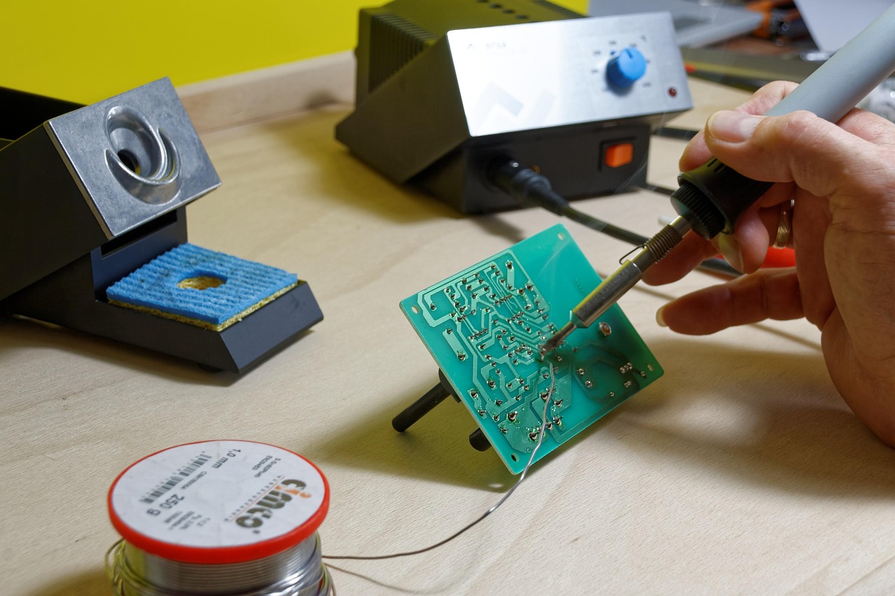
If cleaning the lenses fails to restore normal machine operation, conduct electrical resistance and continuity checks with a digital multimeter to confirm whether the thermistor or phototransistor circuit has suffered an internal failure.
Step 1: Isolate the Wiring Harness
Ensure power is completely disconnected at the main circuit breaker panel. Remove the lower toe kick panel to expose the sump area beneath the tub. Locate the multi-wire plastic connector plugged into the back of the turbidity sensor housing. Press the locking release tab on the connector firmly and pull straight back to unplug the harness.
Step 2: Test NTC Thermistor Resistance
Set your digital multimeter to measure resistance in Ohms (Ω), selecting the 20kΩ or 200kΩ range. Place the fine needle probes onto the two electrical terminal pins corresponding to the NTC thermistor circuit (refer to the schematic tech sheet usually stored inside the lower kickplate or inner door panel for pin identification).
At typical room ambient temperature (approximately 70°F to 75°F / 21°C to 24°C), a healthy thermistor exhibits specific target resistance values depending on the brand design:
- Bosch / European Platforms: Typically measure between 40,000 Ohms (40kΩ) and 60,000 Ohms (60kΩ) at room temperature.
- Whirlpool / KitchenAid / GE Platforms: Typically measure between 9,000 Ohms (9kΩ) and 12,000 Ohms (12kΩ) at room temperature.
- Infinite Resistance (Reading ‘OL’ or ‘∞’): Indicates a completely broken wire or open circuit within the thermistor element. The sensor unit is defective and must be replaced.
- Zero Resistance (Reading 0 Ω): Indicates an internal short circuit. The sensor unit is defective and must be replaced.
- Thermal Response Test: Hold the sensor head in your warm hand or dip it briefly into warm water while monitoring resistance. A functional thermistor will show resistance dropping smoothly as temperature increases. If resistance remains completely static, the internal thermistor is dead.
Step 3: Measure Control Board Power Supply
While taking extreme care to avoid touching exposed wiring, briefly restore circuit power to check the incoming voltage from the main control board to the optical LED circuit. Set the multimeter to DC Volts (V DC). Carefully probe the harness connector terminals coming from the machine. You should measure approximately 5.0 Volts DC across the supply lines. If 5V DC is present at the plug, but the dishwasher reports optical sensor errors with clean lenses, the internal light receiver within the sealed module has failed.
Step-by-Step Sensor Replacement Procedure
Replacing an unserviceable turbidity assembly is a quick, straightforward repair once you have cleared physical access to the sump housing.
1. Source the Proper Direct-Fit OEM Component
Locate the official model number sticker placed along the inner door edge, tub frame, or side door jamb of your appliance. Purchase an exact OEM replacement turbidity sensor assembly matched to that model number. Avoid non-certified aftermarket clones; slight variations in light spectrum output or thermistor resistance response curves will cause ongoing communication errors with sensitive control boards.
2. Prepare the Workspace
Turn off power at the main breaker panel and shut off the water supply valve under the sink. Lay down a thick towel or heavy drop cloth under the dishwasher base. Remove the toe kick plate, lower access covers, and sound suppression blanket.
3. Unfasten and Remove the Faulty Sensor
Reach beneath the sump housing and pull off the electrical connector plug. Depending on the mechanical design of your appliance, release the sensor using one of three standard attachment methods:
- Twist-Lock Mount: Grasp the plastic sensor body, push it inward against the rubber sealing gasket, and twist 90 degrees counterclockwise until the locking ears align with the removal slots. Pull the unit straight out.
- Retaining Wire Clip: Use needle-nose pliers or a small flathead screwdriver to slide off the flexible metal clip securing the sensor against the sump socket, then pull the sensor free.
- Screw Flange Mount: Use a Torx driver to remove the one or two mounting screws securing the retaining bracket flat against the outer sump wall.
### 4. Clean the Sump Insertion Bore
Pull the old sensor module completely out from the sump wall. Keep a towel handy to catch any small dribbles of water exiting the mounting hole. Inspect the circular socket bore on the sump wall. Use a clean, damp cloth to remove any slime, grit, calcium deposits, or degraded rubber particles from the seating surface.
### 5. Install the Replacement Assembly
Inspect the replacement turbidity unit to confirm the factory black or orange rubber O-ring seal is seated smoothly in its channel. Apply a thin coating of food-grade silicone lubricant to the outer surface of the O-ring seal; this prevents the rubber from pinching or rolling during installation and guarantees a watertight seal.
Align the plastic locking tabs on the new module with the slots in the sump socket. Press the sensor firmly into the socket until flush. Twist clockwise 90 degrees until the unit clicks into place, or reattach the retaining clip/screws tightly. Reconnect the electrical wiring harness connector until its locking clip snaps shut.
Post-Replacement Reset and Logic Recalibration
Installing a new turbidity module requires resetting the main control board’s stored diagnostic memory so it learns the baseline light transmittance of the fresh optical lens.
- Clear Saved Memory Error Codes: Restore electrical power at the main breaker panel. Open the dishwasher door and hold the Start/Reset button down for three to five seconds until the display flashes or double-beeps, clearing saved historical fault logs.
- Run an Automated Diagnostic Cycle: Access your appliance’s automated service test sequence (refer to your tech sheet for model-specific button combinations, such as pressing any three option keys in sequence three consecutive times). The system will execute a rapid test program, cycling the water inlet valve, circulation pump, heater, and turbidity sensor to measure clear water baseline values.
- Perform a Test Wash: Load a small batch of dishes and run a standard auto-wash cycle. Verify that the cycle countdown timer advances smoothly, wash water reaches proper temperature, and the cycle completes without triggering error codes or aborting early.
Preventative Maintenance to Extend Sensor Life
Taking simple preventative measures minimizes grease accumulation and mineral buildup on sensitive optical lenses, ensuring reliable long-term performance.
- Verify Household Water Heater Settings: Ensure your home’s water heater delivers water to the dishwasher inlet at approximately 120°F (49°C). Cold water entering the tub causes floating grease and animal fats to solidify on optical lenses before heating elements reach full operating temperature.
- Perform Monthly Descaling Maintenance: Once a month, run an empty heavy-duty cycle using an appliance descaling product or a bowl filled with two cups of white distilled vinegar placed upright on the upper rack. This dissolves thin calcium deposits on the optical lenses before they calcify into thick, opaque crusts.
- Clean Sump Filters Weekly: Remove and rinse the central cylindrical filter under warm running water once a week. Preventing food waste from rotting in the sump basin keeps recirculating water cleaner and prevents grease films from coating the sensor windows.
- Dose Powder and Gel Detergents Correctly: Avoid using excess detergent, especially in homes equipped with water softeners. Oversaturating soft water with detergent causes silica etching on plastic components, permanently clouding optical lenses over time.
Frequently Asked Questions (FAQ)
Can I bypass a dishwasher turbidity sensor entirely?
No. Modern electronic control boards require active feedback voltage from the phototransistor and thermistor to execute wash programs. Bypassing or disconnecting the sensor causes the control board to immediately detect an open circuit fault, halting cycle execution instantly.
Is it safe to clean turbidity sensor lenses with alcohol or acetone?
No. Chemical solvents like acetone or high-concentration rubbing alcohol degrade clear acrylic and polycarbonate plastics, causing clouding, surface micro-cracking, or permanent haze. Stick strictly to mild dish soap, warm water, white distilled vinegar, or citrus descaling fluids.
Why does my dishwasher display a turbidity error code after replacing the sensor?
If a fresh OEM replacement sensor continues to trigger error codes, common causes include an unseated electrical harness connector, oxidation on harness terminal pins, a severed wire inside the lower door hinge wire channel, or a control board that was not properly reset following component installation.
When to Replace the Main Control Board
If you have installed a genuine OEM turbidity assembly, verified harness continuity, cleaned all filter housings, and performed a logic reset, but the appliance still aborts wash cycles or reports persistent soil sensor errors, the failure point lies higher in the control chain.
Before replacing an expensive central control board, use your digital multimeter to check end-to-end electrical continuity along every conductor wire connecting the sensor plug under the sump directly to the main circuit board header pins behind the door panel. A pinched harness wire, broken trace, or corroded connector terminal anywhere along this line prevents signals from reaching the microprocessor. If wiring harness continuity is verified, power delivery is stable, and a fresh turbidity sensor yields no response during service diagnostic modes, replacing the main control board is the final necessary step to restore your dishwasher to full operating condition.