When evaluating an electrical sub panel surge protector vs whole house arrestor US homeowners quickly discover that modern residential power systems require a far more sophisticated defense than a simple plug-in power strip. Today’s modern households are filled with sensitive microprocessors embedded in everything from high-efficiency variable-speed HVAC blowers and induction cooktops to smart home hubs, Level 2 electric vehicle chargers, and delicate solar inverter networks. A single transient overvoltage event—whether triggered by a severe lightning strike on utility infrastructure or an internal heat pump compressor cycling off—can instantly destroy microchips or inflict cumulative, thermal degradation that shortens equipment lifespan.
To establish true electrical resilience, homeowners must navigate three standardized tiers of Surge Protective Devices (SPDs): Type 1 utility-side arrestors, Type 2 breaker-panel suppressors, and Type 3 point-of-use surge strips. Deciding whether to place primary protection solely at the main service entrance or to install secondary suppression at sub-panels depends on your home’s square footage, physical wiring topology, feeder circuit lengths, and the distribution of high-draw appliances. Understanding how these devices function individually—and how they operate in a coordinated, cascaded network—ensures complete protection against both destructive external surges and routine internal electrical spikes.
Understanding Transient Overvoltage: External Grid Surges vs. Internal Voltage Spikes
A transient surge is a high-amplitude, short-duration spike in electrical voltage that significantly exceeds the nominal 120/240-volt single-phase power delivered to American residences. While grid utility power normally flows in a stable, 60 Hertz sinusoidal wave, transient overvoltages can spike to thousands of volts and last anywhere from a fraction of a microsecond to several milliseconds. Despite their brief duration, these intense voltage impulses force excess energy through circuits engineered for much lower thresholds, creating extreme thermal stress, melting microscopic silicon traces, and puncturing delicate dielectric insulation layers inside microcontrollers.
Residential electrical surges fall into two distinct operational categories based on their point of origin: external utility-grid events and internal inductive-switching events.
- External Surges (10% to 20% of total surge events): These represent massive high-energy transients caused by direct lightning strikes, cloud-to-ground strikes on nearby power lines, utility substation grid switching, transformer bank failure, or rapid voltage overshoot following power restoration after a storm blackout. Lightning does not need to strike a residence directly to inflict severe damage; striking a primary utility line miles away can send thousands of surge amperes traveling along overhead drop cables directly into the electric meter socket.
- Internal Surges (80% to 90% of total surge events): These routine spikes are generated continually inside the home’s own branch wiring. Whenever high-draw inductive loads—such as central air conditioning compressors, heat pump units, well pumps, workshop motors, or power tools—shut down, their internal electromagnetic fields collapse instantly. This rapid magnetic decay dumps energy back into the panel busbars as a high-frequency voltage transient. These self-generated micro-surges circulate through house wiring dozens of times each day, degrading sensitive appliances on the same distribution circuit.
Because internal inductive spikes account for the overwhelming majority of power quality disturbances, installing protection exclusively at the main service disconnect leaves downstream electrical equipment vulnerable to internal noise generated throughout the home.
Anatomy of Surge Protective Devices: Type 1, Type 2, and Type 3 Explained
To standardise product safety and performance, the National Electrical Code (NEC) and Underwriters Laboratories (under the UL 1449 4th Edition standard) categorize surge protective devices based on their specific physical mounting location within a residential electrical distribution system.
Type 1 SPDs (Main Service Entrance Arrestors)
Type 1 surge arrestors are installed on the line side of the main service disconnect—positioned between the secondary winding of the utility step-down transformer and the main service panel breaker, or mounted directly within the electric meter socket enclosure. Because Type 1 arrestors sit upstream of all branch overcurrent protective devices, they must feature rugged, weather-rated enclosures and exceptionally high surge-current capacity. They absorb high-energy atmospheric surges before voltage spikes cross into the home’s internal load center, requiring no dedicated branch circuit breaker for operation.
Type 2 SPDs (Panel and Sub-Panel Suppressors)
Type 2 surge suppressors are installed on the load side of the main service disconnect. These units are typically mounted directly inside or flush-adjacent to primary breaker panels and secondary sub-panels. A Type 2 unit connects directly to the panel’s internal phase busbars via a dedicated double-pole circuit breaker (typically rated between 15 and 50 amperes depending on manufacturer requirements). Type 2 suppressors divert residual voltage that bypasses upstream Type 1 devices while actively trapping internally generated inductive surges before they jump across busbar branches.
Type 3 SPDs (Point-of-Use Plug-In Strips)
Type 3 devices include standard surge-suppression power strips, surge-protected wall receptacles, and plug-in module units. By UL guidelines, Type 3 devices must be installed at a minimum conductor length of 30 feet (10 meters) away from the main service panel to ensure proper coordination with upstream protective devices. While Type 3 units provide localized clamping fine-tuning for plug-in electronics like desktop computers and home entertainment systems, they offer zero protection for hardwired appliances such as water heaters, EV chargers, or HVAC outdoor condensers.

Technical Comparison Matrix: Type 1 Arrestor vs. Type 2 Sub-Panel Suppressor
When analyzing an electrical sub panel surge protector vs whole house arrestor US grid applications require reviewing technical specifications to balance performance across each panel level. The matrix below contrasts key engineering parameters:
| Technical Parameter | Type 1 Main Service Arrestor | Type 2 Sub-Panel Suppressor | Type 3 Plug-in Power Strip |
|---|---|---|---|
| Physical Mounting Point | Utility meter socket or line-side main panel lugs | Load-side busbars in main or sub-panels | Standard wall receptacle (min. 30ft wire run) |
| Primary Overvoltage Role | Heavy atmospheric & utility grid spikes | Residual grid energy & internal inductive spikes | Terminal precision clamping for plug-in electronics |
| Nominal Discharge Current (In) | 10kA to 20kA | 3kA to 20kA | 3kA (Maximum testing threshold) |
| Max Surge Current (Imax) | 50kA to 100kA+ per phase | 25kA to 108kA per phase | Low capacity (Joule-rated limits) |
| Voltage Protection Rating (VPR) | 600V to 1000V (Higher let-through) | 600V to 800V (Tighter clamping) | 330V to 500V (Finest voltage floor) |
| Hardwired Equipment Protection | System-wide gross suppression | Targeted sub-panel branch protection | None (Receptacle-connected loads only) |
The Role of Sub-Panels: Why Main Panel Protection Alone May Fall Short
A frequent error among property owners is assuming that a single whole-house surge protective device installed at the primary service disconnect protects every electrical circuit throughout the building. Physics and circuit dynamics demonstrate why long wire runs introduce structural vulnerabilities that single-point protection cannot address.
1. High Conductor Impedance and Voltage Reflection
When an intense surge pulse travels along copper or aluminum feeder cables from a main basement panel to a secondary sub-panel in a detached garage, guest home, or upper level, it encounters physical wire impedance (inductance and resistance). As the high-frequency voltage wave hits the junction or end of a long sub-panel feeder circuit, it undergoes a wave-reflection phenomenon known as voltage reflection. Depending on circuit length and load conditions, this reflected wave can constructively combine with incoming voltage, effectively doubling the peak overvoltage at the remote sub-panel relative to the voltage measured back at the main panel.
2. Inductive Isolation of Sub-Panel Loads
Sub-panels are installed specifically to supply clusters of heavy electrical loads: detached workshop machine tools, swimming pool filtration pumps, ductless mini-split compressors, solar inverter arrays, and high-amperage Level 2 EV charging stations. Every time these high-inductance loads start up or shut off, they create high-amplitude internal transients directly on the sub-panel’s local busbars. A surge suppressor located far away at the primary service entrance cannot clamp these localized spikes quickly enough to prevent them from reaching adjacent electronics powered by that same sub-panel.
Installing a dedicated Type 2 electrical sub panel surge protector vs whole house arrestor US standards recommend guarantees that internally generated spikes are neutralized directly at the sub-panel busbars before traveling through secondary branch circuits.
NEC Code Requirements: Understanding 2020 and 2023 Code Mandates
Residential surge suppression has evolved from an optional equipment upgrade into a strict safety mandate under recent revisions of the National Electrical Code (NEC).
- NEC 2020 Article 242.8 and Section 230.67: The 2020 code cycle introduced a major requirement stating that all dwelling unit main services must be equipped with an integral or adjacent Surge Protective Device (SPD). The code dictates that this device must be a Type 1 or Type 2 SPD, listed to UL 1449 safety standards. This requirement applies to all new home construction and any service panel replacement or upgrade project.
- NEC 2023 Expansion: The 2023 edition expanded this coverage beyond main electrical services to encompass replacement service equipment, feeder sub-panels, and outbuildings served by secondary feeders (such as detached garages, barns, or workshops).
In municipalities enforcing modern NEC editions, local building inspectors will fail a panel upgrade or sub-panel installation if a compliant, UL-listed surge protective device is absent. Placing a Type 2 unit on your sub-panel brings your structure into alignment with safety rules.
Cascaded Layered Protection: The Multi-Tiered SPD Strategy
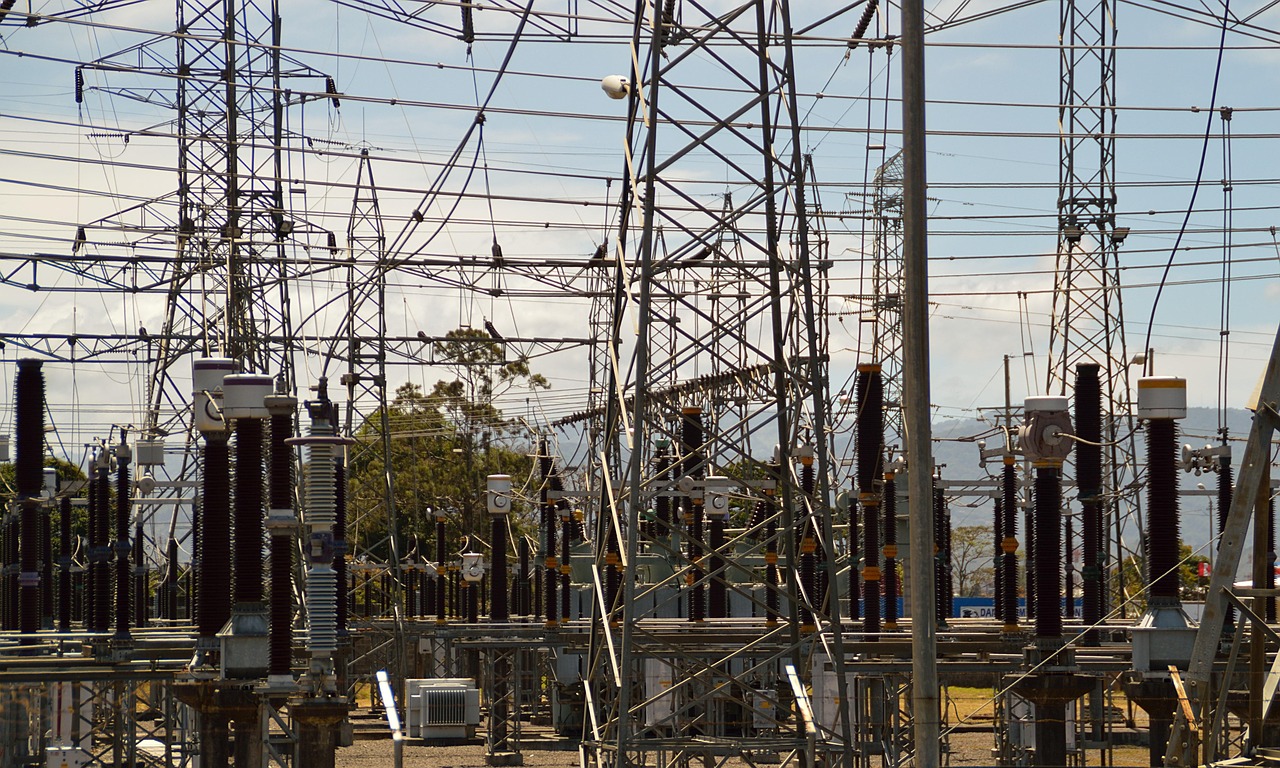
Rather than evaluating meter-base arrestors and sub-panel suppressors as competing choices, electrical safety engineers recommend a comprehensive cascaded protection strategy. No single surge device can filter tens of thousands of surge amperes while simultaneously delivering the low voltage protection floor required by delicate microelectronics.
A multi-tiered defense deploys three distinct protection zones:
- Primary Zone (Type 1 Service Entrance Arrestor): Located at the utility meter socket or main disconnect switch. This unit absorbs high-energy external spikes caused by lightning or utility transformer switching, diverting maximum surge currents straight to the ground rod system and reducing a 10,000-volt transient down to roughly 800 to 1,000 residual volts.
- Secondary Zone (Type 2 Main and Sub-Panel Suppressor): Installed directly on the busbars of primary load centers and downstream sub-panels. This layer clamps residual grid transients that pass through the main entrance while trapping localized motor-switching spikes, reducing transient voltage down to 400 to 600 volts.
- Tertiary Zone (Type 3 Plug-in Strips): Placed at sensitive terminal equipment (audio/video systems, server racks, desktop computers). This final layer fine-tunes remaining voltage ripples down to a safe 330-volt threshold directly at the wall outlet.
This coordinated approach shares the thermal load across multiple devices, extending equipment lifespan and securing the entire home distribution grid.
How Metal Oxide Varistors (MOVs) Function—and How They Fail
To understand why surge devices require periodic replacement, it helps to examine the core internal components inside a standard Type 1 or Type 2 SPD. Modern surge suppressors rely primarily on Metal Oxide Varistors (MOVs), which are non-linear semiconductor components composed of zinc-oxide grains sandwiched between ceramic matrix layers.
Under normal AC operating conditions (120/240V at 60Hz), an MOV maintains extremely high electrical resistance, acting like an open switch that draws negligible leakage current. However, when a transient surge voltage exceeds the MOV’s threshold rating, the component transitions within nanoseconds into a highly conductive state. It shunts excess current around sensitive load equipment straight into the neutral and grounding conductors, clamping line voltage to a safe limit.
The Degradation Mechanism of Sacrificial Components
MOVs are inherently sacrificial components. Every time an MOV diverts a voltage spike, microscopic structural breakdowns occur across its zinc-oxide grain boundaries. While a massive lightning strike can destroy an MOV instantly, routine minor surges degrade the material slowly over several years.
As MOVs degrade, their threshold voltage drops, causing them to leak continuous current and generate internal heat. Modern UL 1449 compliant Type 1 and Type 2 SPDs incorporate internal thermal disconnect fuses. These thermal cutoffs isolate degraded MOVs safely before excessive heat builds up inside the electrical enclosure.
When an internal MOV degrades or its thermal fuse trips, the unit ceases protection. Manufacturers equip modern units with visual LED indicators (green for fully operational, red or unlit for depleted) or audible alarm sounders to notify homeowners that the unit has reached the end of its useful life and requires replacement.
Key Technical Parameters to Evaluate Before Purchase
When selecting a Type 1 or Type 2 SPD for main panels or secondary sub-panels, review the manufacturer’s technical specification sheet for these core parameters:
1. Voltage Protection Rating (VPR)
VPR represents the maximum residual voltage allowed through by the SPD after executing a standard combination surge test (6kV / 3kA wave). Lower numbers indicate superior clamping performance. For typical 120/240V split-phase systems, aim for a VPR of 600V to 700V across Line-to-Neutral (L-N) and Line-to-Ground (L-G) pathways to shield sensitive electronic equipment.
2. Maximum Discharge Current (Imax) per Phase
Imax measures the absolute maximum single-event surge current an SPD can absorb without catastrophic component failure. Residential Type 2 units typically range from 25,000 Amps (25kA) to 108,000 Amps (108kA) per phase. In regions with high lightning activity (such as the US Gulf Coast, Florida, or Midwest), select units rated for at least 50kA to 100kA per phase to ensure long-term durability.
3. Nominal Discharge Current (In)
In measures the peak surge current (typically 3kA, 10kA, or 20kA) that an SPD can withstand for 15 consecutive impulse cycles without suffering performance degradation. A 20kA In rating is the highest testing standard recognized under UL 1449, signifying heavy-duty industrial component quality.
4. Short Circuit Current Rating (SCCR)
SCCR designates the maximum fault current an SPD can safely withstand from the utility without breaching its protective enclosure during a short circuit event. Match or exceed your service panel’s overall fault-current capacity (commonly 10,000A to 22,000A for residential services).
Economic and Practical Decision Matrix: Choosing the Right Setup
To select the ideal protection setup for your property, evaluate these three real-world residential application scenarios:
Scenario A: Single Main Panel, Standard Suburban Home (1,500 – 2,500 sq ft)
- Electrical Topology: All branch circuits, appliance runs, and HVAC compressors originate directly from a central 200-amp main breaker panel in the basement or garage. No secondary sub-panels exist.
- Recommended Protection Strategy: Install a high-capacity Type 2 panel-mounted SPD (50kA to 108kA Imax per phase) on a dedicated 20A to 50A double-pole breaker located directly at the top of the main panel busbars. Supplement with Type 3 plug-in strips at desktop computer workstations and entertainment centers.
- Outcome: Meets full NEC code compliance, protects central HVAC electronics, and delivers cost-effective whole-house coverage.
Scenario B: Single-Family Home with Detached Workshop or Garage Sub-Panel
- Electrical Topology: Main 200A service panel in the main house; a 100A secondary sub-panel located 80 feet away in a detached workshop supplying an EV charger, air compressor, and heat pump.
- Recommended Protection Strategy: Mount a Type 1 or high-capacity Type 2 SPD inside the main house service panel, plus install a dedicated Type 2 SPD inside the garage sub-panel.
- Outcome: Neutralizes voltage reflection along the 80-foot feeder run and isolates inductive motor spikes produced by workshop tools from reaching main-house appliances.
Scenario C: High-Lightning-Density Region with Multiple Secondary Sub-Panels
- Electrical Topology: Home located in high thunderstorm regions (such as Florida or Southeast coastal states) featuring an exterior meter main disconnect, an interior distribution sub-panel, and separate pool/outbuilding sub-panels.
- Recommended Protection Strategy: Install a heavy-duty Type 1 arrestor directly at the exterior meter disconnect, combined with Type 2 SPDs mounted in both the internal load center and the pool/outbuilding sub-panels.
- Outcome: Complete cascaded defense built to withstand severe atmospheric ground potential shifts and intense grid instability.
Installation Best Practices and Common DIY Pitfalls
While deploying a plug-in Type 3 power strip is simple, installing a Type 1 or Type 2 electrical sub panel surge protector vs whole house arrestor US standards dictate opening live panel enclosures and working near energized busbars. Unless you have experience with panel safety and regional electrical codes, hire a licensed electrician to execute the installation.
Essential Guidelines for Maximum SPD Effectiveness:
- Minimize Lead Wire Length and Avoid Sharp Bends: High-frequency surge impulses encounter steep impedance when traveling along conductor wire. Every additional inch of lead wire adds inductance, raising residual let-through voltage into the panel. Keep lead wires as short and straight as possible (ideally under 6 to 12 inches total length) and avoid 90-degree bends.
- Mount Top-Adjacent to Main Lugs or Service Breaker: Install the dedicated double-pole supply breaker for the SPD in the top-most breaker spaces closest to the main lugs or main disconnect breaker. This minimizes current path travel length along internal panel busbars.
- Verify Grounding and Bonding System Integrity: A surge suppressor functions by routing excess energy directly into the earth grounding electrode system. If ground rods are corroded, loose, poorly bonded, or improperly connected to metallic water piping, excess energy cannot dissipate efficiently. Have your electrician inspect ground resistance prior to installing new SPDs.
- Avoid Double-Tapping Panel Breakers: Inserting SPD lead wires into an existing double-pole breaker alongside appliance wires violates NEC standards unless the breaker terminal lug is explicitly listed for dual conductors. Always install panel SPDs on a dedicated double-pole breaker sized according to manufacturer requirements.
Maintenance, Inspection, and Replacement Schedule
Surge protection devices are sacrificial safeguards that degrade over time. Maintaining home protection requires ongoing monitoring and timely unit replacement.
- Bi-Annual Visual Status Checks: Open your breaker panel door twice each year (such as when changing smoke alarm batteries or resetting seasonal clocks) to inspect the diagnostic status LEDs on all Type 1 and Type 2 SPDs. A solid green light indicates active protection. An amber, red, or unlit indicator signals that internal MOVs have depleted and the unit must be replaced.
- Post-Storm Inspections: Following severe thunderstorm activity, direct lightning events in your neighborhood, or prolonged utility grid power outages, inspect panel SPDs immediately to verify that heavy external spikes were successfully clamped without tripping internal thermal cutoffs.
- 5-to-7 Year Replacement Cycle: Even if visual status LEDs show green, MOV components subjected to ongoing utility grid switching degrade slowly over time. Industry experts recommend replacing residential SPDs every 5 to 7 years to ensure optimal clamping voltage protection.
Frequently Asked Questions About Residential Surge Protection
Can I install a whole-house surge protector myself?
Installing a Type 1 or Type 2 surge protector requires working inside an electrical main panel or sub-panel where uninsulated, energized conductors are present. Unless you are trained in electrical safety protocols, local panel code requirements, and proper de-energization procedures, hire a licensed electrician to handle the installation safely.
Will a whole-house surge protector stop direct lightning strikes?
No single residential surge protection device can completely suppress a direct, high-energy lightning strike carrying hundreds of thousands of amperes. However, a properly installed, cascaded Type 1 and Type 2 SPD system will handle indirect nearby strikes and utility-line induced lightning surges, diverting the energy safely into ground rods.
Why did my surge protector light turn red or go out?
When an SPD indicator light turns red or turns off completely, it means the internal Metal Oxide Varistors (MOVs) have absorbed their maximum capacity of electrical surges and the internal thermal fuse has safely disconnected the degraded components. The device is no longer providing surge suppression and must be replaced immediately.
Do sub-panel surge protectors protect against power outages?
No. Surge protective devices protect against high-voltage overvoltage spikes, not voltage drops or power outages. To keep equipment running during a blackout, you need an Uninterruptible Power Supply (UPS) battery backup or a standby generator system.
Final Decision Matrix: Sub-Panel Suppressor vs. Whole-House Arrestor
When evaluating an electrical sub panel surge protector vs whole house arrestor US homeowners should follow this final decision summary:
- For Single-Panel Homes: Install a high-quality Type 2 SPD (rated at 50kA to 108kA per phase) directly in your main electrical load center. This satisfies NEC 2020/2023 mandates, protects hardwired HVAC equipment, and provides basic system-wide coverage.
- For Homes with Sub-Panels or Long Wire Runs: Install a primary Type 2 SPD at the main breaker box and a secondary Type 2 SPD inside every downstream sub-panel. This eliminates voltage reflection issues across long feeder cables and traps local motor-switching spikes directly at the sub-panel.
- For Maximum System Protection: Implement a complete 3-tiered cascaded defense system combining a meter-socket Type 1 arrestor, Type 2 panel suppressors, and Type 3 point-of-use plug-in strips for high-value microelectronics.
By matching your surge protective equipment to your home’s physical layout, equipment distribution, and local code standards, you can effectively defend your high-value appliances, safeguard delicate smart electronics, and maintain electrical safety throughout your property for years to come.