When your kitchen appliance stops keeping milk cold while ice cream stays rock hard in the freezer, a refrigerator evaporator fan motor replacement DIY US project is usually the fastest, most economical fix available. The symptoms usually follow a frustratingly consistent pattern: the freezer stays solidly frozen, but the fresh food compartment steadily climbs into unsafe food preservation temperatures. You might hear a high-pitched chirping, squealing, or rattling coming from behind the rear panel inside the freezer, or perhaps complete silence where a gentle, reassuring hum used to be. For many homeowners, this scenario causes panic about expensive compressor failures or replacing the entire refrigerator. However, the true culprit is frequently a failing evaporator fan motor or a stuck, worn door switch assembly.
The evaporator fan plays an essential role in your appliance’s thermal balance. While the compressor and refrigerant coils extract heat down to sub-zero temperatures inside the freezer cavity, it is the evaporator fan that physically pushes that chilled air through plastic ducts, dampers, and diffusers into the fresh food section. If that fan stops spinning—or if a failed door switch falsely tells the control unit that the door is wide open—cold air stops circulating entirely. In this detailed manual, we will walk through airflow mechanics, systematic multimeter diagnostics, defrost drain clearing, and step-by-step motor replacement to restore your appliance to peak operating performance.
Understanding Airflow Dynamics and the Dual Role of the Evaporator Fan
To troubleshoot cooling problems effectively, you must first understand how cold air moves inside a standard top-freezer, bottom-freezer, or side-by-side refrigerator. Modern home refrigerators sold across North America generally rely on a single primary cooling zone located around the evaporator coil pack in the freezer section. The compressor pumps liquid refrigerant through these coiled copper or aluminum tubes, expanding the gas to draw heat out of the cabinet.
However, without forced convection, that intense cold air would settle exclusively at the bottom of the freezer compartment, leaving your fresh vegetables and dairy warm. The evaporator fan motor sits directly above or behind the evaporator coils behind a removable plastic or sheet-metal access panel in the back wall of the freezer. When activated, the fan blades draw cabinet air across the frosted fins of the evaporator coils. This process drops the air temperature significantly. The fan then forces a portion of this cold air through molded air channels into the refrigerator section via an adjustable mechanical or electronically controlled damper door. The remaining chilled air circulates directly within the freezer cavity.
When the fan fails electrically or mechanically, two distinct symptoms immediately emerge throughout the appliance:
- Temperature Imbalance: The freezer may remain cold enough to keep frozen food intact because of its direct proximity to the cold coils, but the fresh food section climbs to 50°F or higher as circulation stalls.
- Evaporator Coil Frosting: Without continuous airflow to move thermal energy across the coils, radiant cold builds up unchecked on the aluminum fins. Over several days, atmospheric moisture inside the cabinet freezes into a thick jacket of solid ice across the entire coil assembly, further choking off any subtle passive air movement.
The Hidden Culprit: How Refrigerator Door Switches Control Fan Operation
Before ordering a replacement fan motor or disassembling your freezer, you must test the door switch assembly. On almost all modern domestic refrigerators, opening either the fresh food or freezer door automatically turns on the interior cabinet light and simultaneously cuts power to the evaporator fan motor. Manufacturers design the system this way so the fan does not blow warm, humid ambient room air across the freezing coils or blast cold air out into the kitchen while you grab ingredients.
The door switch is a simple mechanical push-button or rocker switch mounted in the cabinet frame. When the door closes, the door edge depresses the switch plunger. Internally, this mechanical action toggles two separate electrical circuit paths (or a single pole, double-throw contact):
- It opens the light bulb circuit, turning the cabinet light off.
- It closes the evaporator fan motor circuit, supplying 120V AC or low-voltage DC to the fan motor.
If the internal electrical contacts controlling the fan circuit corrode, snap, or become misaligned, the control system will continuously assume the door is open. The cabinet light will turn off when the door closes because its contact operates properly, but the fan motor will never receive electrical power. Thousands of perfectly functional fan motors are mistakenly thrown away every year simply because a inexpensive door switch failed to pass power through its secondary contact terminal.
Essential Diagnostic Tools and Safety Preparation
Working on major home appliances requires strict adherence to electrical safety protocols. Before attempting any diagnostic tests or disassembling internal panels, gather the following tools and safety gear:
- Digital Multimeter: Must be capable of measuring AC voltage (up to 200V AC), DC voltage (for modern variable-speed inverter fans), and Resistance/Continuity (Ohms, Ω).
- Nut Drivers and Socket Sets: 1/4-inch and 5/16-inch magnetic nut drivers are standard for securing panel screws on American brands like Whirlpool, GE, Frigidaire, Maytag, and Kenmore.
- Screwdrivers: #2 Phillips and flat-head screwdrivers (preferably with insulated grips).
- Putty Knife or Plastic Pry Tool: Useful for gently releasing plastic door switch retaining clips without marring the inner cabinet liner.
- Safety Glasses and Work Gloves: Evaporator coil fins are thin and razor-sharp, making skin cuts common during panel removal.
- Hair Dryer or Steamer: Needed if heavy ice accumulation must be cleared to reach components without damaging surrounding plastic.
Phase 1: Diagnosing the Refrigerator Door Switch Assembly
Because accessing the door switch takes less than five minutes and requires no major freezer disassembly, always test the switch before taking out shelves or ice makers.
Visual and Physical Inspection
Open the fresh food compartment and freezer doors. Locate the plunger or rocker switch along the inner lip of the cabinet frame. Press the plunger firmly with your thumb. It should spring back instantly when released, offering clean mechanical resistance and an audible click. If the button feels spongy, sticks inside its plastic housing, or rattles loosely, internal spring or contact failure is almost certain.
Testing the Door Switch with a Multimeter
To confirm electrical operation beyond a shadow of a doubt, perform a continuity test on the isolated switch:
- Unplug the refrigerator from the wall outlet.
- Insert a thin putty knife or plastic pry tool beneath the outer flange of the switch housing and gently pop it out of the cabinet liner opening.
- Pull the switch assembly out until the wiring harness connector is fully exposed. Press the plastic locking tab on the wire harness and pull it clear of the switch terminal pins.
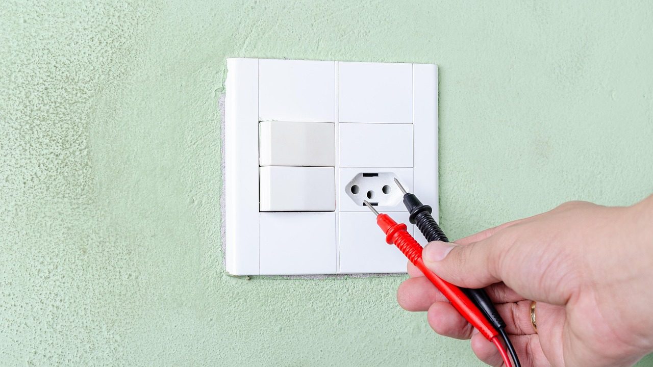
- Set your digital multimeter to the Resistance setting (Ohms, Ω) or the audible Continuity setting (which emits a tone when a circuit is closed).
- Touch one multimeter probe to each terminal pin on the switch. Note that switches with three or four terminals have separate terminal pairs for the interior light and the fan circuit. Consult your appliance’s wiring schematic (often located tucked under the front kick plate, inside the control housing, or stuck to the back outer wall) to identify fan contacts.
- With the switch plunger extended in its natural state (simulating an open door), the meter should read OL (Open Loop) or infinite resistance across the fan terminals, indicating that no electrical current can flow.
- Depress the switch plunger fully with your thumb (simulating a closed door). The meter reading should drop to near 0.0 to 0.5 Ohms, or emit a steady beep, indicating complete electrical continuity.
If the meter remains on OL when the button is fully depressed, the door switch is dead and must be replaced. If the switch passes this continuity check, your airflow failure stems from the fan motor itself, a damaged wiring harness, a frozen defrost system, or a main electronic control board failure.
Phase 2: Isolating the Evaporator Fan Motor and Assessing Frost Patterns
If the door switch is functioning properly, move to the freezer compartment to inspect the fan motor and evaporator coils directly. Unplug the refrigerator and clear out all freezer contents, removable wire shelves, drawers, and ice maker units.
Removing the Freezer Back Access Panel
The evaporator coil and fan assembly are protected behind a molded plastic or sheet-metal panel at the rear of the freezer compartment. Unbolt any ice maker mounting brackets using a 1/4-inch nut driver, disconnect the ice maker wiring harness, and lift the ice maker unit clear. Next, locate and remove the mounting screws around the perimeter of the back wall panel. Some modern panels snap into place along the top or bottom edges using plastic spring tabs—tilt the panel forward from the top edge and carefully lift it out of the freezer cavity.
Analyzing Evaporator Coil Frost Patterns
Before touching the fan assembly, observe the physical condition of the exposed metal evaporator coils behind the panel. The appearance of frost across these fins provides immediate diagnostic clues about the health of your refrigerator:
| Coil Appearance | Probable Cause | Action Required |
|---|---|---|
| Light, even frost distributed evenly across all coils | Normal cooling operation; fan motor or switch failure highly likely | Proceed directly to electrical fan motor testing |
| Heavy, solid ice block completely encasing the coil pack | Defrost system failure (heater element, bi-metal thermostat, or board) | Melt ice with hair dryer; test defrost heater and bi-metal thermostat continuity |
| Ice ball localized on top coil entry point only; rest of coils bare | Sealed system refrigerant leak or compressor inefficiency | Requires professional EPA-certified sealed system appliance repair |
| Coils completely warm, dry, and bone dry; zero frost anywhere | Compressor not running, start relay failed, or control board dead | Test compressor start relay and main power board relay output |
If the coils are encased in a solid block of ice, the fan blade may simply be mechanically locked in place by thermal ice buildup rather than electrically dead. Melt the ice thoroughly using a low-heat hair dryer (taking care not to deform plastic interior liners), clear all meltwater, and proceed to test motor operation.
Phase 3: Testing the Evaporator Fan Motor
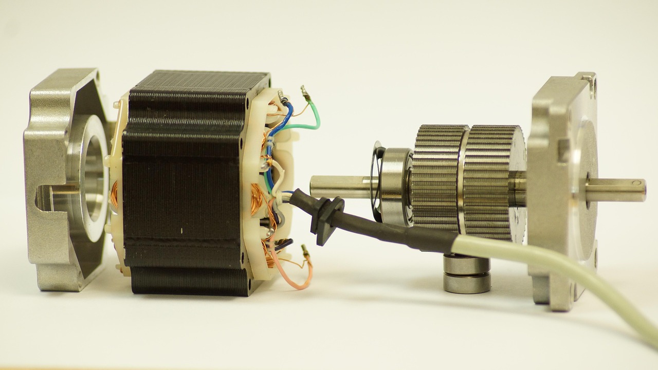
Evaporator fan motors in residential refrigerators generally fall into two categories: traditional single-speed AC shaded-pole motors (found in budget or older models) and modern variable-speed electronically commutated DC brushless motors (found in high-efficiency appliances). Testing methods vary according to motor type.
Testing Standard 120V AC Fan Motors
A standard AC fan motor features two primary power terminals (plus an optional green ground wire attached to its metal frame). To test resistance across the motor windings:
- Ensure power to the appliance is disconnected and pull the two wire leads off the motor spade terminals.
- Set your digital multimeter to the Ohms (Ω) resistance scale (R x 1 or R x 10 setting).
- Place the meter probes onto the two primary motor spade terminals. A functional AC evaporator fan motor should measure between 50 and 200 Ohms of resistance, depending on its horsepower rating and design.
- If the meter reads 0 Ohms, the internal copper coil windings are shorted together. If the meter reads OL (Open Loop), the winding wire inside has broken or burned out. Both conditions mean the motor must be replaced.
- Test for internal frame grounding: Touch one meter probe to the bare metal casing of the motor frame and the other probe to each electrical terminal pin in turn. If you read any numerical continuity, the motor is shorted to ground and presents an electrical shock hazard. Replace it immediately.
Testing Variable-Speed DC Fan Motors
Modern DC motors typically feature three to four wires organized inside a plastic plug connector: ground (usually white or blue), main supply voltage (12V–13.5V DC), speed feedback/tachometer signal wire, and pulse-width modulation (PWM) control input. Measuring resistance across electronic DC motors with a multimeter is often inconclusive because of micro-circuitry inside the motor housing. Instead, evaluate mechanical resistance and harness supply voltage:
- Manual Shaft Spin Test: Grab the fan blade hub and spin it with your fingers. It should spin smoothly and coast freely for a second or two without catching. If you feel gritty resistance, binding, or noticeable radial play in the bronze bushings, the internal bearings have dried out. Squealing or chirping noises during operation stem from worn sleeve bearings, requiring motor replacement even if electrical resistance passes.
- Checking Harness DC Voltage: Re-connect appliance power temporarily, tape down the door switch plunger to simulate a closed door, and carefully measure DC voltage between the ground wire and supply wire at the motor plug using your multimeter set to DC Volts. If 12V DC is present at the plug but the motor refuses to turn, the internal electronic driver board inside the fan housing has failed.
Phase 4: Checking and Clearing the Defrost Drain Line
A frequently overlooked cause of repeated evaporator fan motor failure is a clogged or frozen defrost drain line. Every 8 to 12 hours, the refrigerator control system pauses cooling operation and activates a high-wattage heating element beneath the evaporator coils to melt accumulated frost. This meltwater runs down an angled drain trough into a plastic tube that empties into a shallow drip pan underneath the appliance near the compressor, where ambient heat evaporates the water harmlessly.
If the small drain hole at the bottom of the freezer evaporator coil assembly becomes clogged with food particles, dust, or ice, meltwater cannot escape during automatic defrost cycles. Instead, water pools along the bottom floor of the freezer compartment, refreezes into a solid sheet of ice, and slowly climbs upward cycle after cycle. Eventually, this rising ice sheet reaches the lower tip of the spinning fan blades, creating a loud clicking, tapping, or grinding noise before freezing the fan blade solid and burning out the electric motor windings.
How to Clear a Frozen or Blocked Drain Line
- Locate the small drain funnel opening directly beneath the center of the metal evaporator coils.
- If the drain trough is filled with solid ice, pour hot (not boiling) water into the trough using a turkey baster or squeeze bottle until the ice melts away completely. Avoid boiling water, which can stress and crack cold plastic cabinet liners.
- Insert a flexible tube or a length of 1/4-inch nylon weed-trimmer line down into the drain hole to dislodge internal sludge, algae, or mineral deposits.
- Mix 1 teaspoon of liquid dish soap with hot water (or a mild baking soda solution) and flush it down the drain line using your turkey baster until you hear water draining freely into the drip pan under the appliance.
- Move to the rear of the refrigerator, pull off the lower cardboard access cover, and inspect the flexible rubber duckbill valve or check valve attached to the end of the drain tube. These rubber check valves frequently stick shut with age—pinch them open manually and clean out trapped debris to prevent future water backups.
Step-by-Step Guide to Refrigerator Evaporator Fan Motor Replacement
Once your diagnostic steps confirm that the fan motor is electrically dead or mechanically seized, purchase an exact original equipment manufacturer (OEM) replacement part or high-quality certified aftermarket equivalent. Never attempt to lubricate permanently sealed fan motor sleeve bearings with spray lubricants or household oil; oil breaks down rapidly in sub-zero freezer environments and attracts dust, leading to total motor lockup within weeks.
Step 1: Complete Power Disconnection and Preparation
Unplug the appliance power cord from the wall outlet. Clear all remaining food items out of the freezer and transfer them to an insulated cooler. Remove all freezer shelves, drawers, and back panel retaining screws as detailed in Phase 2. Store screws in a magnetic parts dish so they cannot slip down floor air vents.
Step 2: Remove the Fan Assembly and Blades
The fan assembly is held in place by a metal or plastic mounting bracket screwed into the rear frame of the freezer wall. Follow these precise steps:
- Disconnect the wiring harness connecting the fan motor to the main cabinet wire harness. Press down firmly on the plastic locking tab and pull the connectors apart. Never pull directly on individual wire leads.
- Unbolt the bracket mounting screws using your 1/4-inch or 5/16-inch nut driver.
- Carefully lower the bracket and motor assembly out of the freezer cavity.
- Grasp the central plastic hub of the fan blade tightly with one hand while holding the motor metal shaft with pliers or your other hand. Pull the blade straight off the shaft. If the blade resists, gently pry under the center hub using a flat-head screwdriver. Take careful note of which direction the fan blade faces—installing the blade backward reverses airflow efficiency and ruins cooling performance.
Step 3: Swap the Motor inside the Mounting Bracket
Remove the retaining screws or flexible rubber vibration grommets holding the old motor inside its metal mounting bracket. Slide the old motor out. Insert the replacement motor into position, ensuring that all rubber isolator bushings are properly seated in the bracket cutouts. These rubber grommets absorb motor operational vibration; leaving them out creates loud hums across the kitchen cabinet frame during operation.
Step 4: Reattach Fan Blade and Reinstall Bracket
Push the plastic fan blade onto the shaft of the new motor until it seats securely against the shoulder retainer ring. Verify that the blade turns freely by spinning it manually—it must clear all metal bracket edges without rubbing or catching. Secure the mounting bracket back onto the rear freezer wall using original screws. Plug the wiring harness connector firmly into place until you feel or hear the locking tab click shut.
Step 5: Replace the Door Switch (If Diagnostic Tests Failed)
If diagnostic testing in Phase 1 revealed a faulty door switch, install the replacement switch now:
- Align the wire harness connector with the terminal pins on the new door switch assembly and snap it together.
- Push the switch housing straight into the rectangular cutout in the refrigerator cabinet frame until the flexible plastic retaining tabs lock flush against the liner.
Step 6: Reassembly and Operational Testing
Reinstall the back freezer cover panel, taking care not to pinch internal wiring or misalign air damper openings. Screw the panel down tightly. Reinstall the ice maker unit and reconnect its wire harness if previously removed. Put all shelving and drawers back into place.
Plug the appliance back into the wall outlet. Set fresh food and freezer temperature controls to normal operating ranges (typically 37°F for fresh food and 0°F for the freezer). Close the doors. Within 30 to 60 seconds (or after the main control board completes its internal self-test), you should hear the quiet, steady airflow hum of cold air circulating through the cabinet vents. Open the door—the fan should stop instantly. Press and hold the door switch plunger manually—the fan should resume spinning smoothly within two seconds.
Common DIY Mistakes to Avoid
Completing a refrigerator evaporator fan motor replacement DIY US project saves substantial money compared to professional service call rates, but avoiding common procedural errors is vital for long-term reliability:
- Skipping Door Switch Diagnostics: Replacing a functional fan motor because an inexpensive switch failed wastes time and money. Always verify switch continuity first.
- Installing Fan Blades Backward: Fan blades are pitched specifically to push or pull air in a single direction. Flipping the blade orientation drastically reduces CFM (cubic feet per minute) airflow, leaving the refrigerator compartment warm.
- Neglecting Defrost Drain Lines: Ignoring ice pooling under the coils guarantees the new motor will freeze up within weeks if water backs up and refreezes again.
- Misunderstanding Universal Replacement Motors: Some generic universal fan motors feature reversible rotation achieved by flipping the central rotor shaft. If you install a universal motor spinning in reverse, air flows backward through your appliance, causing freeze-ups in air ducts. Always verify rotation direction before securing access panels.
- Force-Prying Cold Plastic Panels: Cold plastic liners become brittle. Allow the freezer cavity to warm slightly or use warm air from a hairdryer to soften plastic clips before prying on panels to prevent cracking cabinet walls.
When to Call a Professional Appliance Technician
While fan motor and door switch replacements fall well within standard DIY capabilities, certain advanced symptoms point to deeper system issues requiring specialized EPA-certified tools:
- Sealed System Leaks: If the evaporator fan spins properly and defrost systems function, but coils show a single localized ball of ice or zero frost despite continuous compressor operation, your unit has lost refrigerant charge.
- Main Control Board Relay Failures: If power does not reach the fan or switch wire leads, and continuity tests prove wiring harnesses are intact, the electronic micro-relay on the main control board may be burned out.
- Inverter Compressor Drive Faults: Variable-capacity inverter compressors rely on high-voltage DC control circuits that require advanced electrical diagnostic procedures and board diagnostics.
By following this methodical diagnostic manual—testing door switch contacts, checking coil frost patterns, measuring motor winding resistance, clearing drain channels, and securing proper fan alignment—you can confidently solve refrigerator cooling failures, avoid unnecessary replacement costs, and restore consistent temperature control to your home kitchen.