Maintaining pure, high-quality drinking water in your home requires regular attention to your under-sink filtration hardware. Performing complete reverse osmosis water filter sanitization and membrane replacement US homeowners rely on ensures tap water remains free from foul odors, microbial growth, and dissolved heavy metals. Whether you operate a classic multi-stage system with a pressurized storage tank or a modern, high-output tankless reverse osmosis setup, following a disciplined, professional maintenance routine protects both your family’s health and your household plumbing investment.
Residential reverse osmosis (RO) units rely on a carefully orchestrated sequence of physical filtration and chemical adsorption. When sediment pre-filters become clogged or carbon block stages exhaust their capacity to neutralize chlorine, aggressive chemicals reach the delicate semi-permeable RO membrane. Left unchecked, this chemical exposure degrades the filtration matrix, reduces water production at the dedicated dispenser tap, and allows bacterial slime to colonize internal tubing lines and storage reservoirs. This comprehensive guide details the exact steps required to inspect pre-filters, sanitize tanks, replace spent membranes, adjust pressure bladders, and troubleshoot post-maintenance operational issues.
Understanding Your Reverse Osmosis System Architecture
To carry out effective maintenance, you must understand how municipal or well water moves through a residential under-sink reverse osmosis unit. Standard residential RO systems process raw supply water through three distinct functional phases: pre-filtration media, primary semi-permeable membrane separation, and post-filtration polish and storage.
1. The Pre-Filter Stage
Cold feed water enters the system directly from your home’s main plumbing valve via a dedicated angle stop adapter. The initial barrier is typically a melt-blown polypropylene sediment pre-filter, engineered to capture visible physical debris such as rust flakes, silt, sand, and pipe scale down to 5 microns. Positioned immediately after the sediment stage are one or two carbon block filters constructed from extruded activated carbon. These carbon stages adsorb volatile organic compounds (VOCs), synthetic chemicals, and, most critically, strip out chlorine and chloramines added by municipal treatment utilities for disinfection.
2. The Semi-Permeable Membrane
Once cleared of abrasive sediment and oxidants, pressurized water reaches the reverse osmosis membrane housing. Constructed from thin-film composite (TFC) polyamide material coiled tightly around a perforated central core tube, this membrane features filtration pores measuring approximately 0.0001 microns in size. Under water line pressure, water molecules are forced through the microscopic pore structure, rejecting heavy metals, dissolved minerals, fluorides, lead, microplastics, and viral pathogens. Contaminated reject water (brine) flows out through a restricted drain line to your home’s drain pipe, while purified water (permeate) flows toward storage.
3. Post-Filtration and Storage
In traditional undersink systems, purified permeate water flows slowly into a pressurized metal or plastic storage tank containing an internal food-grade butyl rubber air bladder. Because flow through a 0.0001-micron membrane is slow (yielding only drops per minute), the pressurized tank holds 2 to 4 gallons of ready-to-use water. When you open the dedicated kitchen counter dispenser faucet, compressed air behind the bladder pushes pure water through a final activated carbon post-filter (often called an inline GAC polishing filter) to strip away residual storage odors before filling your glass.
Establishing a Workable Filter Replacement Schedule
Maintaining high water purity requires replacing consumables before performance degrades. While exact replacement timing depends on daily household consumption and incoming water hardness, baseline schedules provide a reliable framework for preventive care.
| System Component | Filter Media Type / Function | Recommended Replacement Frequency | Primary Operational Failure Indicators |
|---|---|---|---|
| Stage 1 Pre-Filter | Melt-Blown Polypropylene Sediment | 6 to 12 Months | Dark orange/brown staining, restricted faucet flow |
| Stage 2 & 3 Carbon Blocks | Extruded Bituminous Carbon Block | 6 to 12 Months | Chlorine odor/taste, rapid membrane degradation |
| Stage 4 RO Membrane | Thin-Film Composite (TFC) Polyamide | 24 to 36 Months | TDS rejection dropping below 85-90%, low output |
| Stage 5 Post-Filter | Inline Granular Activated Carbon (GAC) | 12 Months | Stale, flat, or metallic taste at dedicated faucet |
Failing to replace sediment and carbon pre-filters on time is the single leading cause of premature RO membrane failure. Free chlorine present in municipal tap water rapidly oxidizes and burns microscopic holes into TFC polyamide membranes, permanently destroying their capacity to reject total dissolved solids.
Essential Tools, Parts, and Safety Supplies
Before disconnecting quick-connect plumbing fittings or unscrewing filter canisters, assemble all necessary tools and sanitation supplies. Having the right equipment organized on hand reduces service time and prevents accidental water damage under your sink cabinet.
- Replacement Filter Set: A complete filter kit matched to your exact system make and model (including sediment filter, carbon block cartridges, inline GAC post-filter, and a fresh TFC membrane if due for replacement).
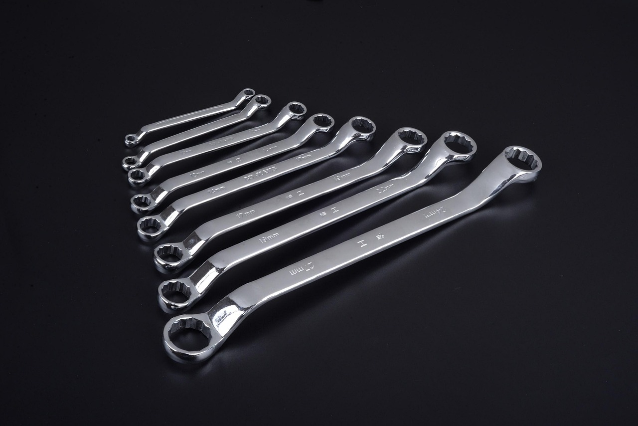
- Filter Housing Spanner Wrench: A circular plastic wrench designed specifically to fit the external ribs of your vertical filter housing canisters.
- Sanitizing Agent: Unscented, plain household liquid bleach (5.25% to 6% sodium hypochlorite concentration) or an NSF-certified liquid RO sanitizing solution. Never use scented, splashless, or thick gel bleaches.
- Digital TDS Meter: A handheld Total Dissolved Solids tester to evaluate membrane rejection efficiency in parts per million (PPM).
- Tire Pressure Gauge & Bicycle Hand Pump: A low-pressure digital gauge capable of accurate readings in the 1 to 15 PSI range, paired with a standard manual bike pump.
- Food-Grade Silicone Grease: NSF-61 certified pure silicone lubricant to preserve rubber O-rings and create watertight seals. Never use petroleum jelly (Vaseline).
- Catch Basin and Shop Towels: A shallow plastic tray or baking sheet alongside clean absorbent towels to catch water trapped inside filter sumps.
- Nitrile Gloves: Disposable powder-free gloves to handle fresh filter cartridges and prevent skin oils or bacteria from contaminating new media.
Pre-Maintenance Safety and System Isolation Procedures
Working on pressurized under-sink plumbing lines without proper depressurization will cause water to spray across cabinet interiors. Follow this safety isolation sequence before loosening any housing canister:
- Shut Off Main Feed Water Supply: Locate the cold water angle stop valve under your kitchen sink. Turn the valve knob clockwise until it stops turning. If your system uses a feed water adapter or saddle valve, close it completely.
- Isolate the Storage Tank: Locate the small blue or blue-and-white lever valve on top of the storage tank. Turn the valve handle 90 degrees (perpendicular to the tubing line) to seal existing water inside the tank.
- Depressurize the Lines: Flip open the dedicated RO dispenser faucet handle on top of your sink counter. Allow any residual water pressure to vent until flow stops completely. Leave the dispenser faucet handle open during filter removal.
- Disconnect Power Connections: Unplug electric booster pumps, leak-detection shutoff solenoids, or inline ultraviolet (UV) sterilization lamps from wall electrical outlets.
Step-by-Step Pre-Filter Inspection and Replacement
With system pressure fully vented, you can safely open the lower vertical filter sumps to inspect and replace spent sediment and carbon cartridges.
1. Unscrewing Filter Canisters
Place your plastic catch basin directly underneath the vertical filter housing assembly. Slide the plastic spanner wrench up onto the first vertical canister housing (Stage 1 sediment filter). Viewing the canister from above, turn the wrench counter-clockwise to break the initial thread friction. Carefully unscrew the housing canister by hand, keeping it upright because it remains completely filled with water.
2. Inspecting Spent Media
Pour the standing water into your collection basin and lift out the old filter cartridge. Inspect the exterior surface of the sediment pre-filter. A light tan or yellowish discoloration indicates standard trapping of rust and micro-silt. A heavy, dark brown or slimy black coating points to significant sediment loading, suggesting you should shorten your filter replacement interval from 12 months down to 6 months.
3. Cleaning Housing Interiors
Examine the inside surfaces of the plastic filter canisters. Over time, physical fine sediment and biological film settle at the bottom of the sumps. Wash the interior of each canister housing using warm tap water, mild liquid dish soap, and a soft nylon brush. Rinse thoroughly to remove all soap residue before installing new filters.
4. Inspecting and Lubricating O-Rings
Locate the black rubber O-ring sitting in the top channel groove of each filter canister. Carefully remove the ring, wipe it clean with a towel, and inspect it for micro-cracks, flattening, or tears. Replace damaged O-rings immediately. Apply a thin, even coat of NSF-61 certified food-grade silicone grease along the rubber ring to maintain elasticity, ensure a tight seal, and prevent rubber pinching during canister reassembly.
5. Installing New Cartridges and Hand-Tightening
Wearing clean nitrile gloves, unpack fresh sediment and carbon block cartridges. Drop each cartridge vertically into its designated canister housing, ensuring the filter seats evenly over the alignment guide peg located in the bottom center. Screw the canister back onto the manifold bracket by hand turning clockwise. Ensure the threads catch smoothly. Hand-tighten firmly, then use the spanner wrench to apply a final quarter-turn. Over-tightening with a wrench can crack plastic threads or pinch rubber O-rings, leading to high-pressure leaks.
Sanitizing the RO Storage Tank and System Tubing
Because reverse osmosis systems remove chlorine residual from feed water, purified water stored inside holding tanks is susceptible to slow, dark bacterial growth over time. Sanitizing the storage vessel and fluid lines every 12 months eliminates biofilm, maintains water safety, and prevents stale tastes.
1. Completely Draining Standing Water
Before introducing liquid sanitizer, empty the holding tank entirely. With the main cold water feed valve closed, open the storage tank top valve and allow the dedicated countertop RO faucet to drain until the tank feels light and water stops dripping.
2. Adding Sanitizing Liquid Solution
Remove the pre-filter cartridges from the Stage 1 and Stage 2 filter housings. If performing routine annual maintenance, sanitize while the old filter media is out and fresh cartridges are ready to go in. Pour approximately 2 to 3 tablespoons (1 fluid ounce) of fresh, unscented household bleach directly into the bottom of the empty Stage 1 sediment filter canister sump.
Reattach the empty Stage 1 canister to the manifold bracket. Bypass or remove the delicate central TFC reverse osmosis membrane according to your manufacturer’s instructions, as exposure to concentrated chlorine solutions will damage the thin-film composite polyamide layers.
3. Filling and Pressurizing for Contact Time
Turn the cold feed water supply valve back on, allowing incoming water to fill the filter housings, carry the chlorine solution through internal tubing lines, and fill the pressurized storage tank. Once water begins trickling out of the open countertop dispenser faucet, shut the faucet valve to allow the storage tank to fill completely under line pressure (10 to 15 minutes).
Allow the sanitizing solution to soak inside the storage tank, housing channels, and distribution lines for a minimum of 30 to 45 minutes. This contact duration kills biological colonies and neutralizes lingering bacterial film throughout internal pathways.
4. Flushing Sanitizer from System
Open the countertop dispenser faucet fully to drain the entire sanitized contents of the storage tank into your sink drain. Turn the feed water valve back on to let fresh incoming water partially fill the tank a second time, then drain it completely once more. Continue flushing until you no longer smell bleach at the faucet spout. Once the system is rinsed clear, turn off supply pressure, reinstall your clean pre-filters and RO membrane, and prepare to re-commission the unit.
Evaluating and Replacing the Reverse Osmosis Membrane
The TFC reverse osmosis membrane is the core component responsible for stripping dissolved minerals, heavy metals, and micro-contaminants from drinking water. While pre-filters require frequent replacement, high-quality membranes last between 24 and 36 months when pre-filters are properly maintained.
Testing Rejection Performance with a Digital TDS Meter
Rather than replacing an expensive membrane based strictly on calendar time, test its actual rejection efficiency using a digital Total Dissolved Solids (TDS) meter. Measure raw tap water TDS first, then measure purified permeate water collected directly from the RO tap. Calculate rejection efficiency using this standard formula:
Rejection Rate (%) = [(Tap Water TDS - RO Water TDS) / Tap Water TDS] x 100
For example, if your incoming tap water measures 280 PPM and your purified RO water measures 14 PPM, your rejection calculation is:
[(280 - 14) / 280] x 100 = (266 / 280) x 100 = 95% Rejection
A functional residential TFC membrane achieves between 90% and 98% rejection efficiency. When your measured rejection rate drops below 85%—or if permeate water production slows down despite fresh pre-filters and correct tank air pressure—the membrane element is end-of-life and must be replaced.

Step-by-Step Membrane Replacement Steps
The reverse osmosis membrane is located inside a separate, high-pressure horizontal vessel mounted across the top or back of the filter bracket assembly.
- Disconnect Supply Tubing: Push the outer quick-connect collet ring flat against the fitting collar while pulling the plastic inlet tube straight out from the membrane housing cap.
- Unscrew Housing End Cap: Firmly unscrew the heavy plastic end cap from the horizontal vessel. Use channel lock pliers gently if thread scale makes the cap hard to turn by hand.
- Extract Old Membrane Element: Use clean needle-nose pliers to grip the raised center plastic stem of the old membrane element. Pull firmly outward while twisting gently to slide the element out of the cylindrical housing barrel.
- Sanitize Housing Interior: Wipe down the inner walls of the plastic vessel using a clean towel lightly moistened with mild sanitizing spray or water.
- Install Fresh TFC Membrane: Unpack the new membrane element, handling it only by the center stem while wearing clean nitrile gloves. Verify that the large rubber brine seal cup points toward the open inlet cap end. Apply a light layer of food-grade silicone lubricant to the double O-rings located on the narrow end stem. Push the membrane firmly into the housing vessel until you feel it seat into the inner bottom socket.
- Reattach Cap and Connect Fittings: Inspect the housing cap O-ring, apply silicone grease, and screw the cap back onto the vessel tightly by hand. Reinsert the plastic fluid tube into the quick-connect fitting until it bottoms out, then pull back gently to lock the collet ring in place.
Maintaining Tankless Reverse Osmosis Systems
Tankless reverse osmosis filtration units utilize high-capacity membrane elements (rated between 400 GPD and 1000 GPD) paired with high-pressure internal booster pumps to produce fresh, real-time purified water without a storage tank. While these space-saving designs remove tank contamination risks, effective tankless reverse osmosis maintenance requires distinct care protocols.
Managing High-Output Membranes
Because tankless membranes operate under higher driving pressure and rapid flow velocities, mineral scale deposits build up faster across the membrane surface. High-quality tankless units integrate automated auto-flush valves that direct a quick burst of feed water across the membrane face for 15 to 30 seconds upon startup or after specific operational run times. Periodically inspect your drain saddle line to confirm this high-velocity purge discharge operates correctly during unit startup.
Cleaning Optical and Pressure Sensors
Tankless systems rely on internal micro-flow meters, electronic pressure switches, and optical water sensors to trigger the internal booster pump when you turn on your kitchen dispenser tap. Over time, mineral scale or fine sediment can cloud sensor windows. When replacing drop-in twist-lock composite cartridges on a tankless system:
- Inspect exposed sensor manifold ports and electrical contact pins for moisture or mineral crusting.
- Descale internal fluid channels using manufacturer-recommended citric acid flush cartridges if your unit experiences intermittent flow error warnings.
- Reset internal electronic filter-life indicator displays following the manufacturer’s button-hold sequence after locking new composite cartridges into the unit chassis.
Checking Storage Tank Pressure and Air Bladder Health
A common consumer service complaint is low water output or slow delivery from the RO faucet despite brand-new pre-filters. In the vast majority of traditional tank-based setups, this issue stems from an under-pressurized or damaged internal air bladder.
How to Check Tank Pre-Charge Pressure
Standard under-sink storage vessels contain an internal rubber bladder that separates purified water from an surrounding air chamber. As water fills the tank, it compresses the air pocket. Opening the countertop faucet releases this air pressure, forcing the rubber bladder upward to push water up to your glass.
- Close the main feed water supply valve and open the countertop RO dispenser tap until the tank empties completely. Leave the dispenser tap open.
- Locate the standard Schrader air valve stem (identical to a car or bicycle tire valve) located behind a small plastic cap on the side or lower wall of the tank shell.
- Attach a low-pressure digital tire gauge to the valve stem.
- Read Pre-Charge Pressure: An empty storage tank should register between 5 and 7 PSI of static air pre-charge pressure.
- Adjust Air Pressure: If pressure measures below 5 PSI, use a manual bicycle hand pump to add air in small increments until the gauge reads exactly 7 PSI. Never use high-volume air compressors, which can instantly rupture the thin internal bladder.
Bladder Failure Warning: If liquid water squirts out of the Schrader air valve stem when you press the central release pin, the internal rubber bladder has suffered a structural tear. The storage tank cannot hold air pressure and must be discarded and replaced.
Post-Maintenance System Re-Commissioning
Once you have replaced filter elements, sanitized internal housings, and verified tank pre-charge pressure, re-commission the system following a controlled sequence to avoid air locks, pressure spikes, or minor leaks.
- Verify Tubing Connections: Double-check that all plastic tubing runs are inserted firmly into quick-connect push fittings. Slide blue safety locking clips into place behind collet collars.
- Slowly Open Water Supply: Turn the main cold water feed valve counter-clockwise one-quarter turn to allow incoming water to enter filter housings gradually. Listen for air escaping through the open dispenser faucet spout.
- Perform Leak Checks: Dry all plastic sumps, caps, and quick-connect elbows with a paper towel. Inspect every joint closely for 5 minutes to ensure no micro-beads of water appear around canister threads or tube ports.
- Flush Fine Carbon Dust: Fresh activated carbon blocks release fine black carbon particles upon initial wetting. Allow raw feed water to pass through open filters and out the dispenser faucet continuously for 5 to 10 minutes until the water runs crystal clear.
- Close Dispenser and Charge Tank: Close the countertop dispenser faucet and open the blue top valve on the storage tank. Allow the system to produce purified water uninterrupted for 2 to 3 hours until the automatic shut-off valve cuts incoming water flow.
- Discard Initial Tank Volume: Open the countertop dispenser faucet and drain the entire first full tank of water into your sink drain. Allow the system to refill and drain a second full tank. This double flush purges lingering sanitizer traces and conditions the new filter media. The third tank of purified water is safe for daily drinking.
Troubleshooting Common Post-Maintenance Issues
Even when following precise maintenance protocols, minor operational anomalies can occur after servicing an under-sink reverse osmosis system. Use this quick reference matrix to identify and resolve common issues.
Issue 1: Sputtering Dispenser Flow and Cloudy White Water
Underlying Cause: Tiny air bubbles trapped within the fine microscopic pores of fresh carbon block media and dry TFC membrane coils.
Correction Protocol: This condition is harmless, non-toxic, and temporary. Running 3 to 5 gallons of water through the system purges trapped air pockets. Cloudy water in a clear glass will clear completely from the bottom upward within 30 to 60 seconds.
Issue 2: Wastewater Runs Continuously Down the Drain
Underlying Cause: A failing Automatic Shut-Off Valve (ASOV), incoming household cold water pressure dropping below 40 PSI, or a fouled drain line check valve.
Correction Protocol: Test household line pressure using a pressure gauge. If supply pressure measures below 40 PSI, install an electric booster pump kit. If feed pressure is adequate, test the 4-way ASOV block by letting the storage tank fill completely; if brine water flow down the drain line continues past 3 hours, replace the ASOV block assembly.
Issue 3: High TDS Output After Installing New Membrane
Underlying Cause: The new TFC membrane element is not fully seated into the internal bottom socket of the pressure vessel, allowing untreated feed water to bypass the membrane matrix.
Correction Protocol: Shut off supply pressure, depressurize lines, unscrew the horizontal membrane cap, and push the center stem firmly until you feel the double O-rings seat completely into the internal manifold socket.
Issue 4: Unpleasant Odor or Metallic Taste After Service
Underlying Cause: Residual bleach sanitizer trapped in system lines, an expired inline post-carbon polishing filter, or debris inside the faucet aerator tip.
Correction Protocol: Perform an extra full fill-and-drain flush cycle on the storage tank. Unscrew the small aerator tip from the countertop dispenser spout, soak it in white vinegar to clear mineral deposits, rinse thoroughly, and thread it back onto the faucet tip.
Summary Maintenance Checklist for US Homeowners
Consistent care keeps under-sink filtration systems running safely while protecting home plumbing from leaks. Attach this summary routine inside your sink cabinet for convenient reference:
- Every 6 Months: Replace Stage 1 sediment pre-filters and Stage 2/3 carbon block cartridges. Inspect rubber O-rings and apply food-grade silicone grease.
- Every 12 Months: Perform complete bleach or chlorine-free system sanitization. Replace the inline post-carbon polishing filter. Test empty storage tank pre-charge air pressure and adjust to 7 PSI using a manual pump.
- Every 24 to 36 Months: Test purified water TDS against raw tap water using a digital meter. Replace the thin-film composite (TFC) reverse osmosis membrane element if total rejection drops below 85-90%.
- Every 5 Years: Inspect all flexible polyethylene tubing lines for stiffness, discoloration, or brittleness. Replace old quick-connect collet clips, pressure regulators, and saddle valves to mitigate long-term leak risks.
By executing these systematic sanitization, replacement, and inspection protocols, you ensure your home reverse osmosis system consistently delivers pure, great-tasting drinking water while extending equipment service life for years to come.